Electric Control Line 101
If you are new to electric powered control line here is a very brief simplified overview of how it all works.
Motor
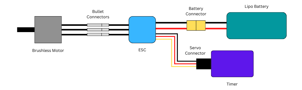
The motor of choice is a brushless out-runner motor. In a brushless motor the commutation of the current to the motor windings takes place outside the motor by a separate electronic device called an electronic speed controller or ESC for short. In an out-runner motor the rotors permanent magnets rotate around the outside of a stationary iron core with copper motor windings. The motor has three wires, one for each set of windings, connected to the ESC with ‘bullet’ style connectors.
Battery
The most popular battery used today is the lithium-polymer (Lipo) battery. The number of cells (at 3.7 volts each) determines the nominal battery voltage. The capacity is measured in milli-amp-hours (mAh). For example: In theory at least, a 1000 mAh battery can supply 1000 mA, or 1 amp, of current for 1 hour. If the current is used at a higher rate the battery would be discharged in a shorter period of time. If the same battery is asked to supply 10A of current (10 X capacity rating) then the battery would be depleted in 6 minutes (1/10 of 1 hour). The maximum discharge rating of a battery is expressed as a ‘C’ rate. A 20C or 25C rating is sufficient for control line use. The style of connector used on the battery can vary and is a matter of personal preference.
ESC
The microcontroller inside the ESC controls the high current components to switch the battery voltage into the 3 phase voltage profile used by the motor. The small 3 wire connector (a ‘servo type’ or ‘Dupont’ connector) from the ESC would normally plug into the throttle position on an RC receiver. For control line purposes the timer replaces the RC receiver. Most ESC’s include a separate voltage regulator circuit called a battery eliminator circuit (BEC). The voltage output of the BEC is connected to the red wire in the middle of the servo connector. The black (or brown) wire is the ‘ground’ wire. The third wire (yellow, orange or white) is the pulsed signal input to the ESC. This digital signal is generated by the timer to communicate the desired throttle setting to the ESC.
Timer
The traditional flight for a control line model is to fill the tank with fuel, start it up and fly until it runs out of gas and then land. A timer is used to simulate that same basic flight profile plus a lot more. Timers allow for a timed delay between initial activation and when the motor starts up. The flight time (length of time that the motor is running) can also be adjusted. The timer also outputs the throttle setting for the desired motor RPM during the flight.