Climb_and_Dive v1.5.3
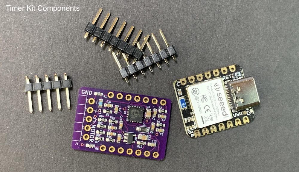
Bill of Materials
Complete project kits can be purchased on Lectronz. Most users choose to order a fully assembled timer. The following instructions are provided if you want to assemble your own for maximum customization. All kits come complete with the program code already installed and the circuit boards fully tested.
If you prefer to purchase items separately here are some suggested sources:
| Qty | Description | Online Sources |
|---|---|---|
| 1 | Seeed Studio Xiao nRF52840 (The cheaper one, not the ‘Sense’ version) | Digikey Mouser Seeed Studio |
| 1 | Climb_and_Dive Backpack w/ 5 pin RA Header Strip | Lectronz |
| 1 | JST Battery Connector (Optional) | HobbyTown Amazon |
Tools Required
Electronic soldering equipment; soldering iron, flux and solder. These are available from numerous sources online. If you need to brush-up on your electronics soldering skills there are some good tutorials on Adafruit and Sparkfun. You will also need a set of diagonal pliers or wire cutters and a small spring clamp.
Do not use a strong acid based flux. While this type of flux is great for home plumbing repairs and building fuel tanks, it can be very corrosive to fragile electronic circuitry. Be sure to only use a rosin based or no-clean type flux suitable for electronics assembly.
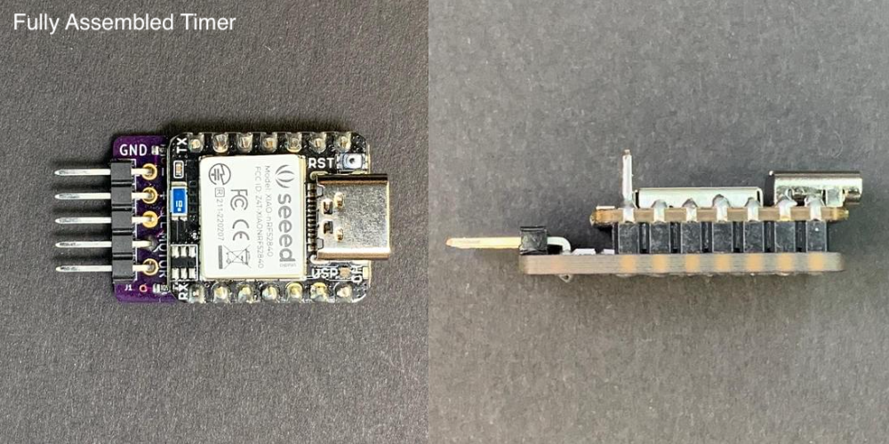
Timer Assembly
The boards as supplied include strips of breakaway header pins. Assemble and solder as shown in the photos below. Be careful to orient the boards correctly. The USB C port must be on the end opposite the ESC/Motor connection pins.
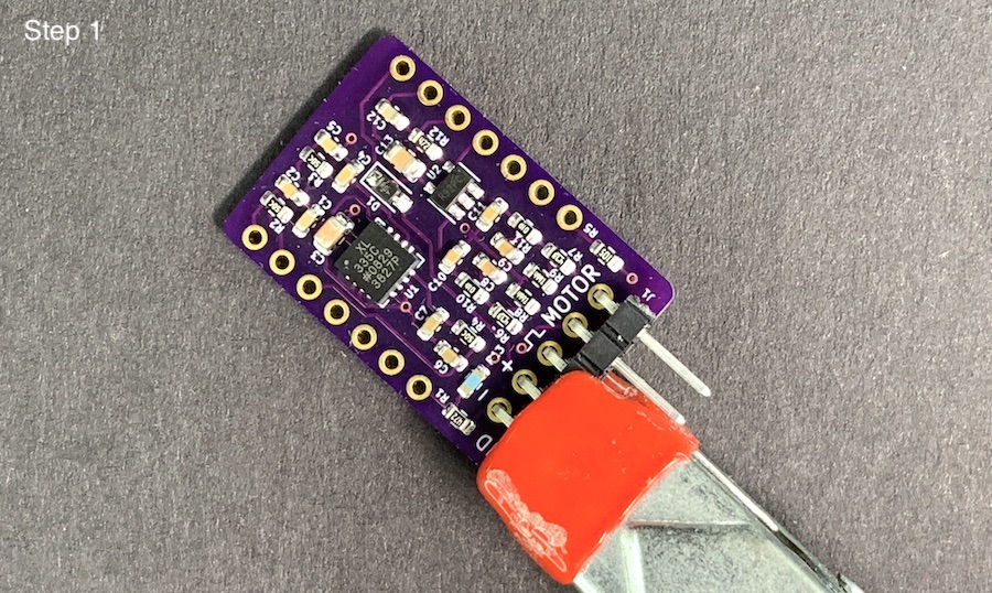
Step 1 - Insert the bent legs of the 5 pin right angle strip through the backpack PCB and hold with a clamp for soldering.
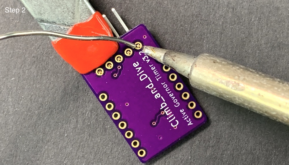
Step 2 - Solder the pins to the back side of the backpack as shown.
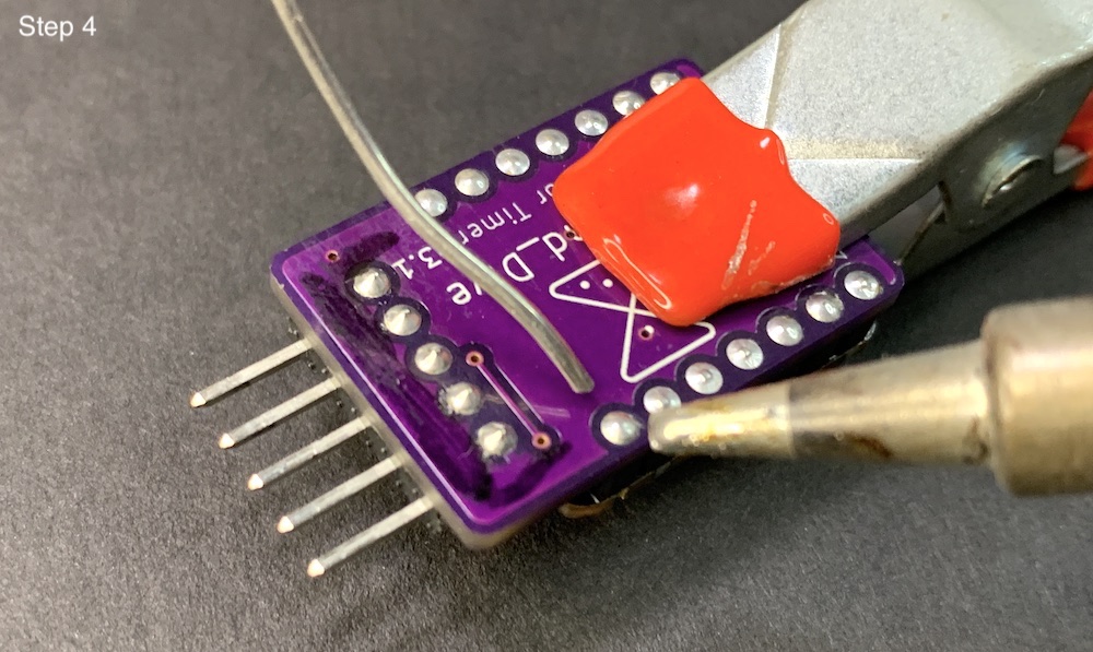
Step 3 - Insert the short legs of the 7 pin header strips through the holes on the top of the backpack. Then stack the Xiao on top of the long pins and clamp together for soldering. Make sure it is orientated as shown.

Step 4 - Solder all of the short header pins on the back of the backpack.
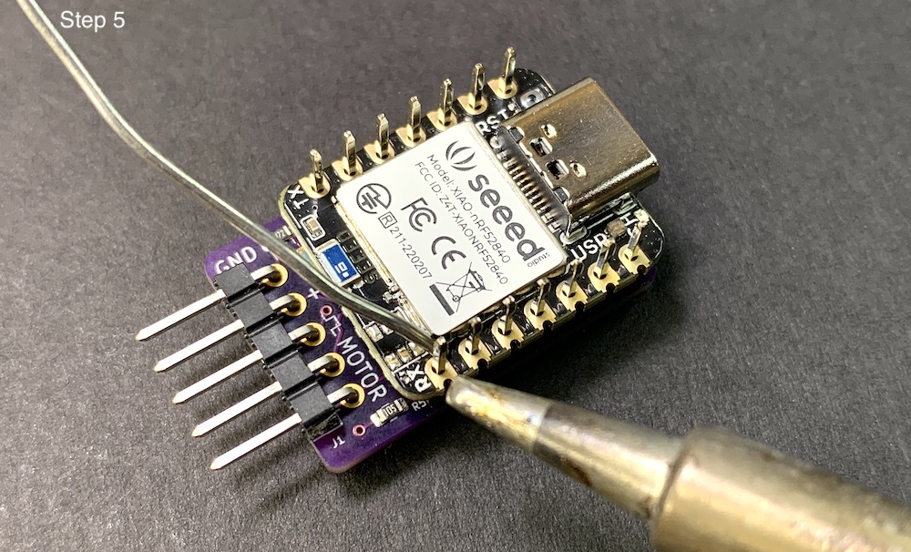
Step 5 - Flip it over and solder all of the longer header pins on the Xiao nRF52840. Don’t trim the long pins just yet.
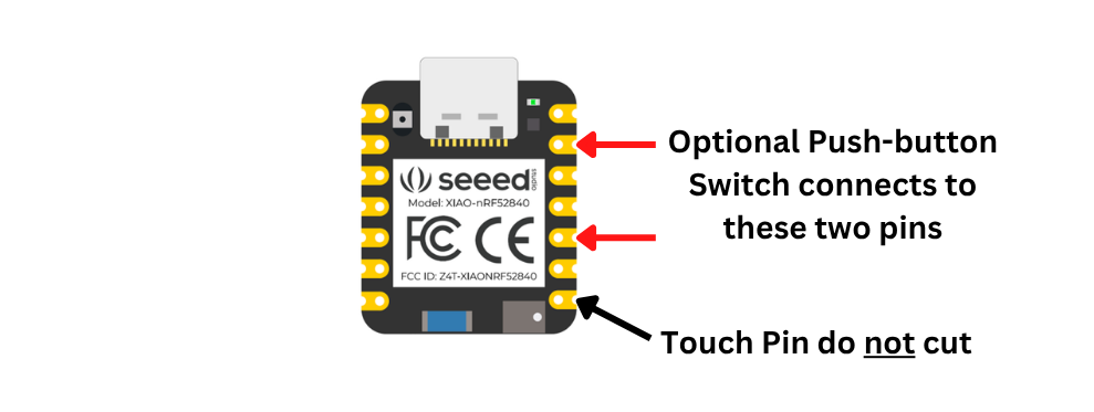
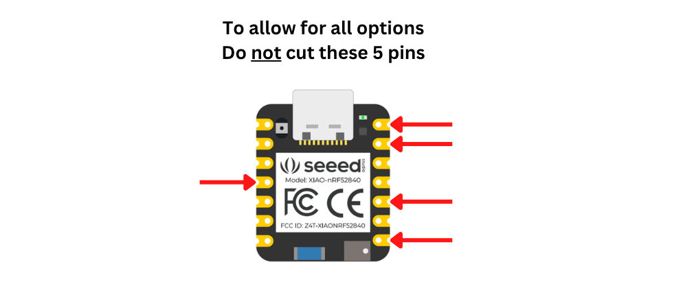
Step 6 - At this point you can trim off only the long header pins that you don’t need. You have some choices to make. First off, do not cut the touch pin, leave it sticking out.
Next, decide if you would like to add an optional push-button switch to use instead of the touch pin. The push-button switch connects to two timer pins. Depending how you want to connect your switch, you may want to leave those two pins sticking out as it makes connecting the switch much easier. The push-button switch functions exactly the same as the touch pin. Note: you must use a normally open (NO) momentary contact type switch. The touch pin will remain usable and works in parallel with the push-button switch. A push-button switch connects to the timer using the 2 pins as shown below.
Next, decide if you would like to add an optional remotely mounted addressable LED status indicator light. See the Advanced Modifications page for details. An addressable LED uses three timer pins. Again, leaving these pins sticking out can make future connections much easier. An LED connects to the timer using the 3 pins as shown below.
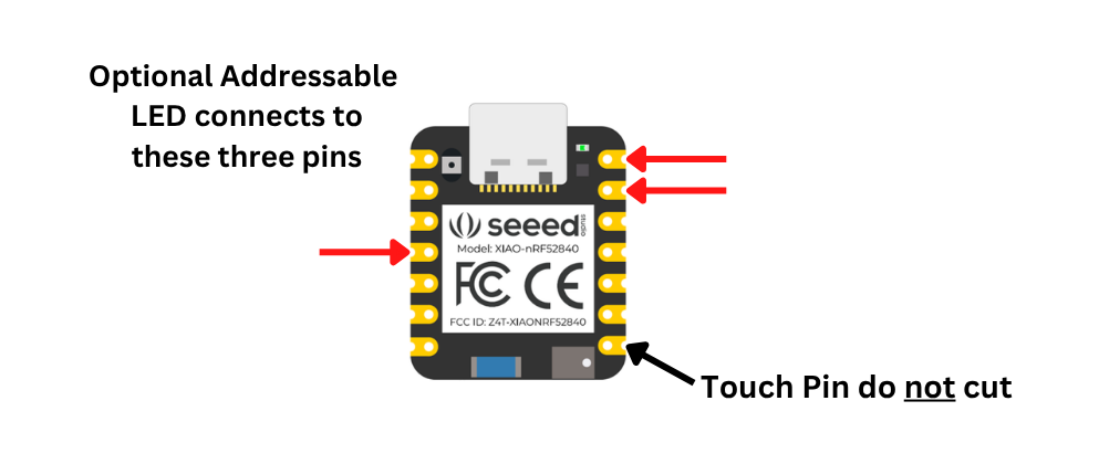
I recommend that you leave all options available. In that case, you need to leave all 5 pins untrimmed as shown below. This configuration is the best for attaching the accessory Control_Panel remote interface.
Step 7 - Optional: It’s a good practice to remove any residual solder flux from the joints. You can do this by using an old toothbrush dipped in 99% Isopropyl alcohol, gently scrubbing away the remaining flux. This high-concentration alcohol is readily available at your local drug store.